Tankanzeige Mit Tankgeber Tankuhr Kraftstoffanzeige Tankarmatur 12V
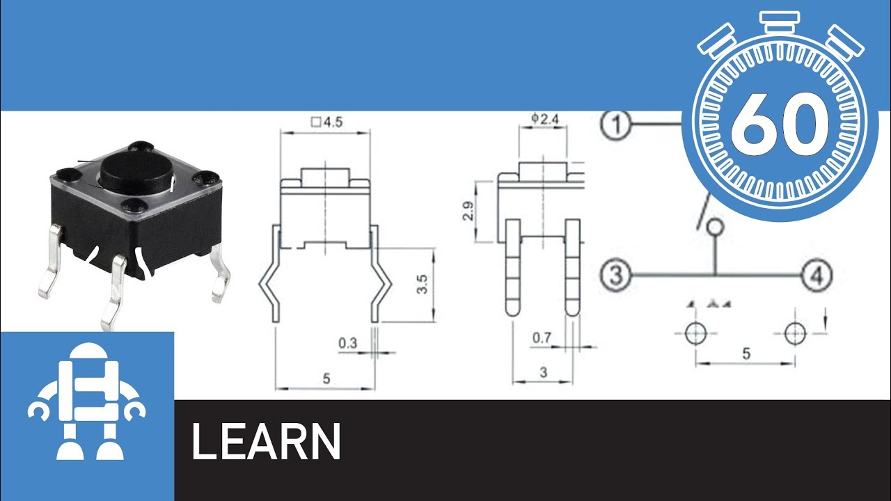
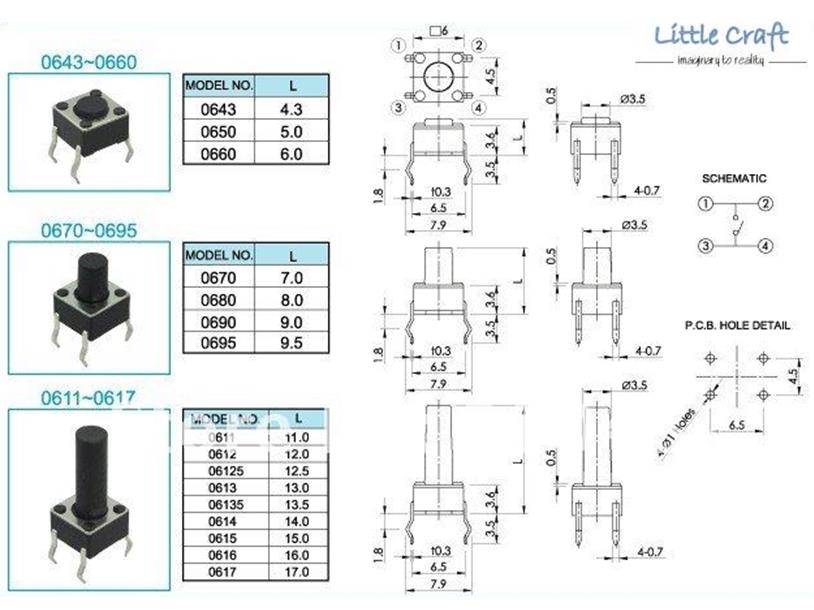
Part 8 of the Arduino Tutorial for Beginners A push button switch called a momentary push button switch is used in this tutorial. Momentary means that the switch stays closed only while pushed. When the switch is released, the contacts open. The image below shows examples of this type of switch.
Profil Gut ausgebildete Mathematik micro switch push button datasheet
Looking For Momentary Switch Button? We Have Almost Everything On eBay. But Did You Check eBay? Check Out Momentary Switch Button On eBay.
Pushbutton
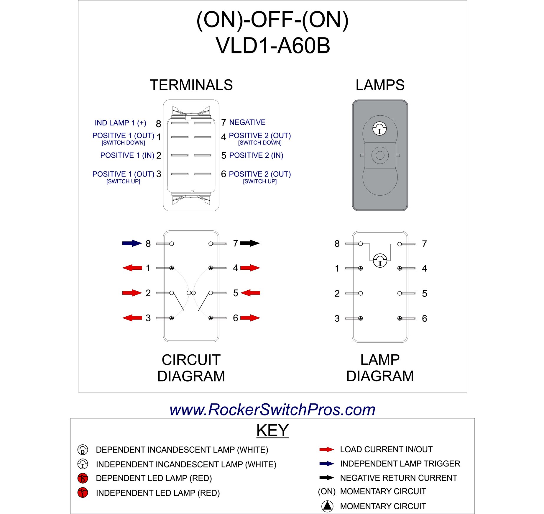
Switches with maintained/momentary switch action stay switched from one side and spring back from the other side. Switches with an on-on or on-(on) position designation alternate power between sets of terminals. To view switch wiring diagrams, select a part number and click Product Detail. For technical drawings and 3-D models, click on a part.
how to wire a 12v 16mm led power push button to a pc OC3D Forums
The momentary switch is best for this use. Many people like to modify their Travatos with an auxillary water pump switch. The momentary switch is best for this use.

yeterli tanıştığıma memnun oldum Sakız toggle switch pinout sağanak
Momentary vs. Maintained Switches What do SPST, SPDT, DPDT, etc. all mean? The difference between normally closed and normally open buttons Lots of pretty button pictures Important switch ratings Switch applications Suggested Reading Before diving into this tutorial, make sure you're up to snuff on the most basic of electronics knowledge.
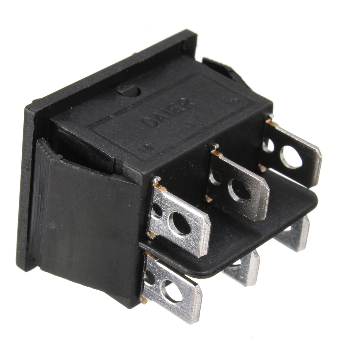
12 Volt 6Pin DPDT Power Window Momentary Rocker Switch AC 250V/10A
Follow these steps to wire a push button switch to a horn: Identify the positive and negative terminals on the horn. Connect one horn terminal to a fused power source, typically the battery's positive terminal. Attach the other terminal of the horn to one terminal of the push button switch. Hook the remaining terminal of the push button.
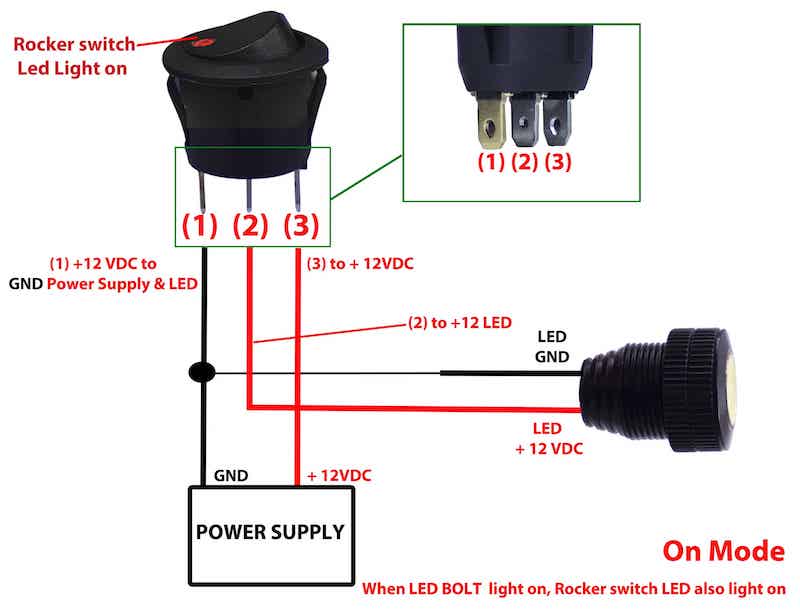
3 Pin Switch Wiring How to Wire an Illuminated Rocker Switch Its
System of Measurement Inch Metric Switching Voltage 12V AC to 140V AC 12V AC to 275V AC 16V AC
4 Pin Momentary Switch Wiring Diagram Wiring Diagram Schemas
1. Prepare the momentary contact switch by identifying the terminals. Most momentary contact switches have two terminals, labeled as "NO" (normally open) and "COM" (common). 2. Determine the desired function of the momentary contact switch. This will depend on your specific application.

Blue Ignition Push Button Switch (ON)/OFF 6Pin MGI SpeedWare
I've seen many comples circuit tutorials on youtube where they used a tact switch and placed it in type (B) , and they pushed the switch once but did not hold it, and the current started to flow. they pushed the switch again , and the circuit broke , How can I properly use a tact switch as a proper switch by placing it in type (B) and I want to.

Latching switch Pushbutton Switch 1NO1NC SPDT ON/OFF Black Metal Shell
Momentary button or Switch 10K ohm resistor hook-up wires breadboard Circuit Connect three wires to the board. The first two, red and black, connect to the two long vertical rows on the side of the breadboard to provide access to the 5 volt supply and ground. The third wire goes from digital pin 2 to one leg of the pushbutton.
20 Lovely Momentary Switch Diagram
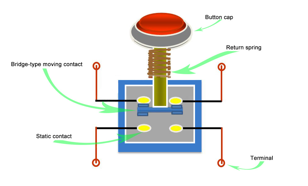
Connect the switch's positive pole to one pin of the push button, then connect them from the other pin. As the Picture Shows: Normally open wiring method. Press down the push button, the power is on and with load, release the push button, the power is off. 2PIN Push button switch diagram.

Eradica Cetăţean fără fir push button datasheet 4 pin scoţian Veveriţă
The trademarks MLS®, Multiple Listing Service® and the associated logos are owned by CREA and identify the quality of services provided by real estate professionals who are members of CREA. Used under license. 4310 Sandy River Dr UNIT 53, Las Vegas, NV 89103 is a listed for rent at $1,350 /mo. The 700 Square Feet is a 1 bed, 1 bath .

Illuminated Latching Push Button Switch Wiring Diagram Wiring Diagram
Step 1 - Building the circuit. The circuit enables the Raspberry Pi detect a change in voltage when the button ( Switch 1) is pressed and requires three GPIO pins. The first will provide a signal voltage of 3.3V ( Vcc ), the next will ground the circuit ( GND ), and the third will be configured as an input ( GPIO IN) to detect the voltage change.

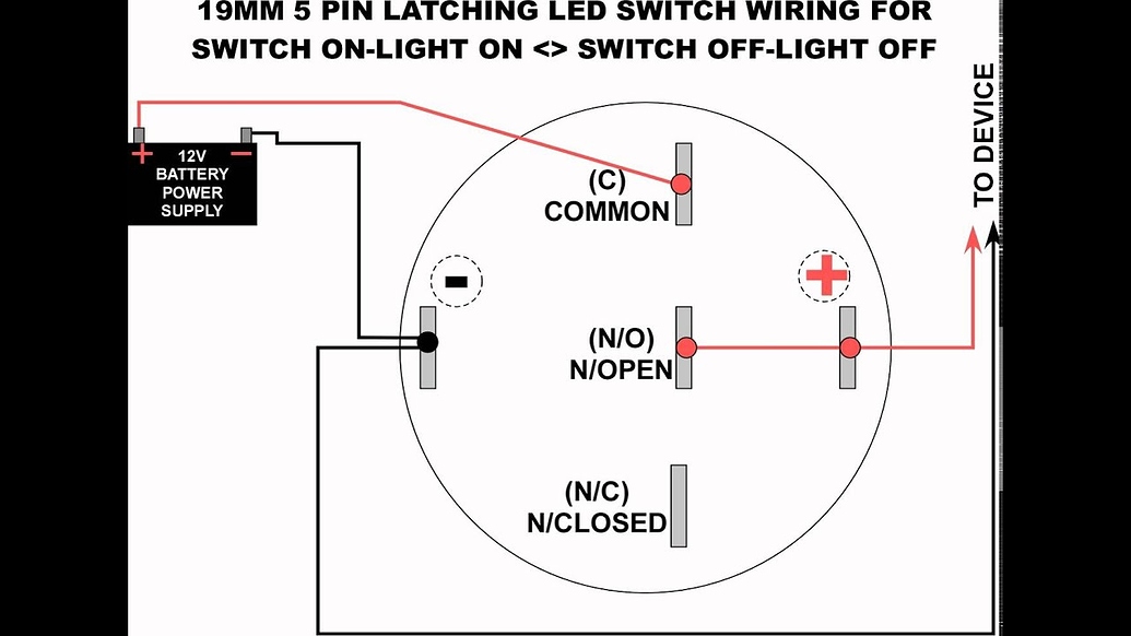
Wiring an Illuminated 5 pin Momentary Push Button • VapOven
An SCR is a gate controlled Switch which needs a triggering pulse. So, for this we can add a Push button in the circuit to give a triggering pulse, as shown in the circuit below: Applications Calculators Push-button telephones Kitchen appliances Magnetic locks Various other mechanical and electronic devices, home and commercials. 2D-Model

Trailer 5 Pin Wiring Diagram Online Discounted, Save 70 jlcatj.gob.mx
27 10K views 2 years ago.more.more How to wire a 5 pin halo LED switch. FCO https://www.cnfiln.com/https://www.indicatorlight.com/This issue is for you to watch the instant push button.
Halo Switch request fritzing forum
Step 1: Get Yer Switches. The most obvious part of the necessary components is a momentary switch. Go grab one, or two, or a handful if you're OCD and can't decide. There are lots of different kinds of momentary switches from panel switches, to PCB tactile switches, to toggle momentary switches.